FSR Mini v2: Tape Mods
In my unboxing and software setup of the pad, you’ll know that I immediately attempted to tape mod the panels that had non-zero readings at idle. I spent a few hours figuring out what does what, and these are my findings.
Whilst I’m at it, I’ll just mention it now that we’ve been calling this phenomenon floating values as they ‘float’ above zero.
Not the Usual Mod You’re Thinking
I’ve been told that, at least for FSRs, tape modding is particularly unreliable and can reduce their working lifespan.
That’s true if your intention is to increase the sensitivity (and let’s not forget these are FSRs after all, the threshold can be adjusted). However, the problem I’m tackling here is different: the panels are applying too much pressure on the sensors as they are.
We need to give the FSR some space. But where do we do that?
Padding
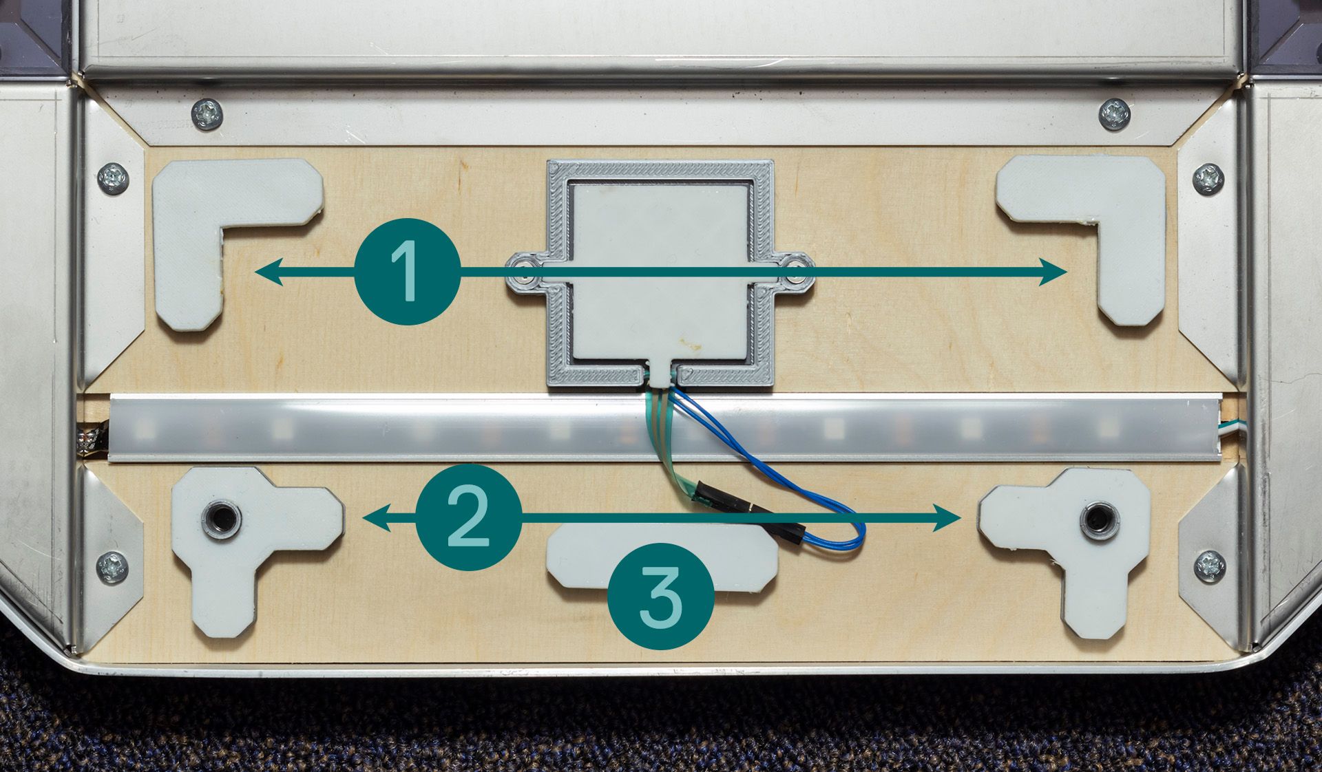
All padding, except for the FSR itself of course, are viable spots to reduce contact with the sensor. There seems to be three main areas:
- The pair on the front FSR side (“big L”)
- The pair that houses the screws on the back side (“small L”)
- The thin horizontal padding directly behind the FSR (“island”,
however you could consider this the biggest L out of the three, if you get my vibe)
The easiest way to add tape is to apply it to the panel instead of directly on the padding. The padding material can be taken off from its housing (or even come off by itself if it manages to stick to the panel as you take it off). Besides, the surface of the panel is flat, whilst the L paddings aren’t = less adhesive potential.
Dingoshi’s tip: If you don’t plan to put tape on the panels, at least put something over the contact areas (e.g. thin plastic sheet) so the panel is protected from damage.
Whilst it’s unlikely the material of these paddings will cut into the panel, at least have something that won’t cause the sticking. Masking tape kinda does the trick.
Big L
At first glance, the most straightforward solution would be to raise the areas where it’s closest to the sensor – the big Ls. Unfortunately, you can’t rely on this alone.
Padding the corners with the intent of putting less pressure on the centre means that you’ve caused the corners to become the most insensitive area due to the bulk that was added on.
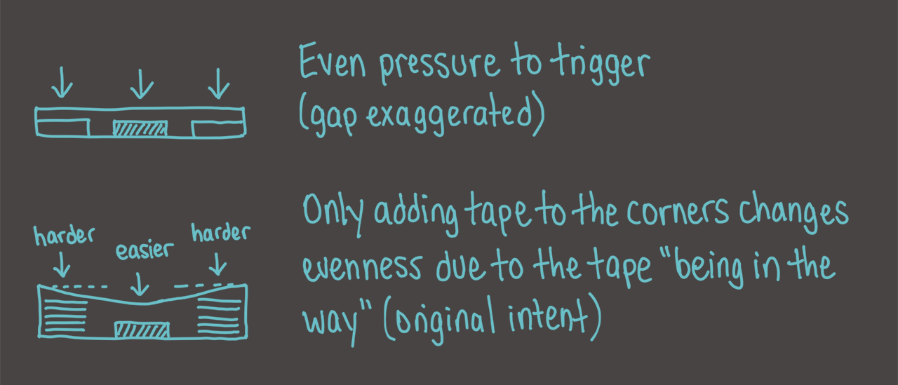
Whilst you could get away with doing this for ←/→, it’s likely you won’t on ↓/↑: your feet would have to angle towards the centre, which promotes non-optimal form.
So whilst it’s probably fine to put a few pieces of tape here, we can’t put too much.
Island
The next best option would be to think orthogonally. The FSR is at the front, so why not try increasing pressure at the back? If you push down on the island, the sensor values do indeed significantly drop, and when you release it, it goes back up again. We might be onto something here.
This strat, as I apply two then one layers of masking tape at a time, worked for ↓ and →, and I was able to reduce their values close to 0 without compromising too much on the big Ls taking away the corner sensitivity.
The only issue was ↑. Surprise, surprise. It always has to be up, doesn’t it. However, in its defence, simply resting the panel on without screwing it in already gave floating values, so it only makes sense that this one would end up using way more layers of tape (around 13 – 16) compared to the others (5 – 7) before it was at an acceptable level. It’s not zero (getting it to that point would require stepping quite hard), but at least it’s not 20%.
A technique as unorthodox as my futurestep
It’s worth knowing that if the island gets raised enough, the panel will start to lean its weight onto the sensor. When you screw the panel in, the pressure will lift the panel back up straight.
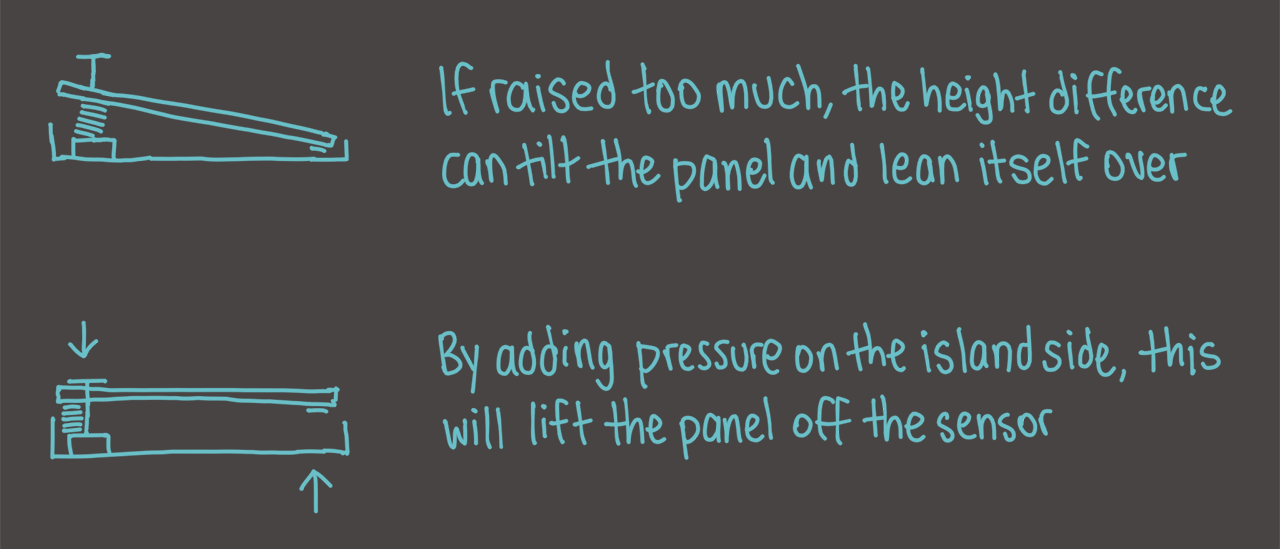
Although I say “too much” as if it’s an undesirable thing, this is a valid “black magic” technique we use in the public arcade – by itself, simply resting the panel triggers the inner sensor, but not when the brackets and screws go on. It’s a reliable way to maintain that immensely subtle raise which proves useful for players with slide form (allegedly useful; I’m yet to be enlightened of this form). However, this method often defies logical thinking; you just use feeling[1].
So, what does all that translate to on the sensor readings?
- A high value as the panel sits freely on the pad
- Whilst you screw the panel in, the reading drops as it lifts itself off the sensor
- But! If you keep tightening the screw, the tape will compress, the panel overall becomes closer to the pad, and the reading goes back up again
When that happens, you need to dial back and loosen the screw, if allowing. If not, because it’d make the screw too loose to stay on (or some other reason) – you need moar tape.
Small L
That leaves the last pair of padding, which I... actually don’t know what it does, or why it does what it does, when I add tape to it.
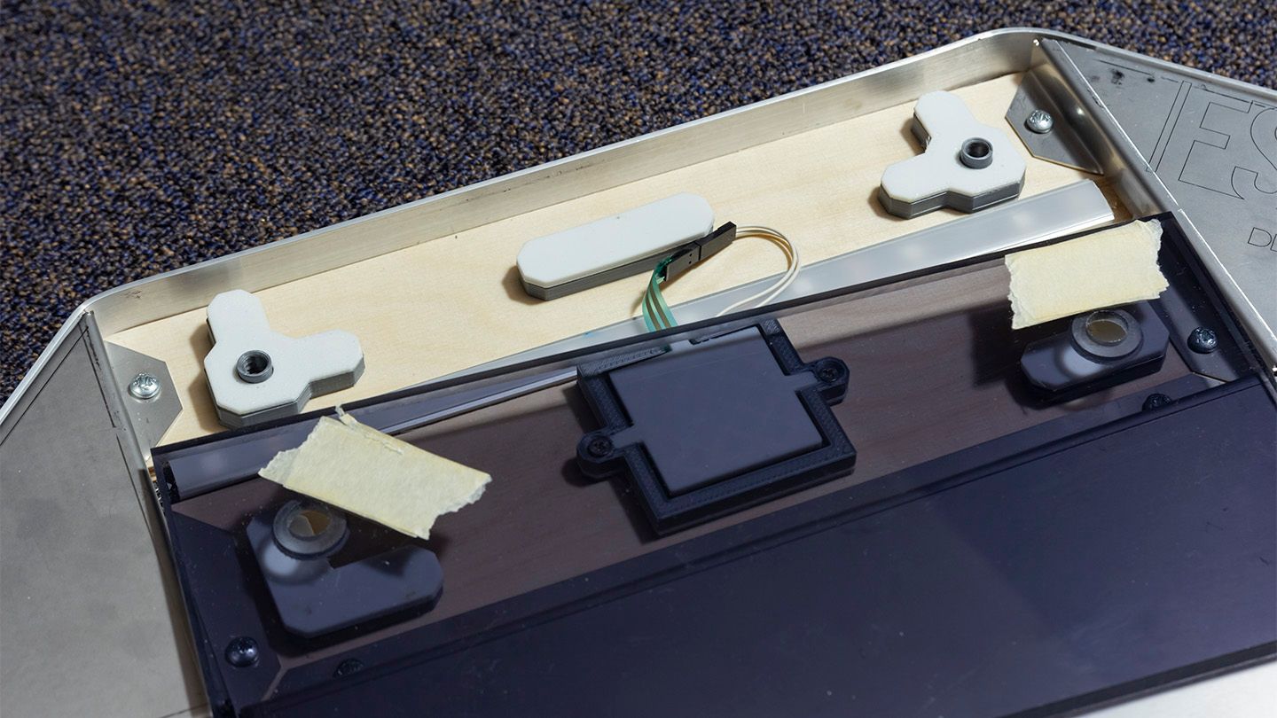
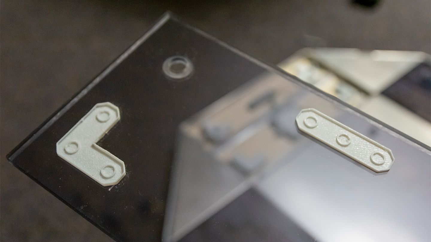
Due to how the screw is in the way, I could either angle the tape 45° so that it covers two edges for the most even raise (left in the image), or place it parallel to the long edge behind the screw (right).
In either situation, what this actually did for me was greatly increase the floating value, rather than my original impression of decreasing it, once I placed the screws on. It wasn’t even doing the value dip; it was just constantly rising the more I tightened the panel.
My initial goal of modding was to reduce the sensitivity of the panel. With the fact that taping the small Ls seemed to demonstrate the opposite of that, I haven’t pursued trying to thoroughly figure out what’s up.
As of currently, the tapes on the small L areas do exist on both the other panels ↓ and →, but I’m under the impression that
- They contribute in some part to the overall pad sensitivity (less likely), or
- They only contribute to evenly raising the back half of the panel, i.e. along with the island (more the case), or
- Straight up isn’t really doing anything (probably this, given how much tape is on the island).
Holes on the panel
It might also be useful to note in the above picture that the holes that are drilled for the screws in the panel can be best described as “countersunk”. The underside is completely smooth; the way the panel is held down by the screw is via the size difference of the holes.
It’s much easier explained if you look at the picture above; I just wanted to bring attention to it.
Calibration
The relationship between resistance and mass on an FSR is inversely proportional rather than linear, so if you want to make each sensor provide the same reading for a certain mass applied, it’s very likely that’s only going to be the case for that specific mass; how each sensor will get to that value may differ.
Like I mentioned in the previous article, I put a dumbbell on the panel above each FSR and Configurated each sensor in the Mapping tab until they had a reading of around 70%. The change in configuration value seems to drastically change around 15 to 30% on the slider.
The slider maps to the resistorValue value in the JSON save file, where 0% is 255 and 100% is 0. I had the following values:
← 110 (57%)↓ 112 (56%)↑ 222 (13%)→ 201 (21%)
From here, I can then test the panels out and set appropriate thresholds. Here’s what I have:
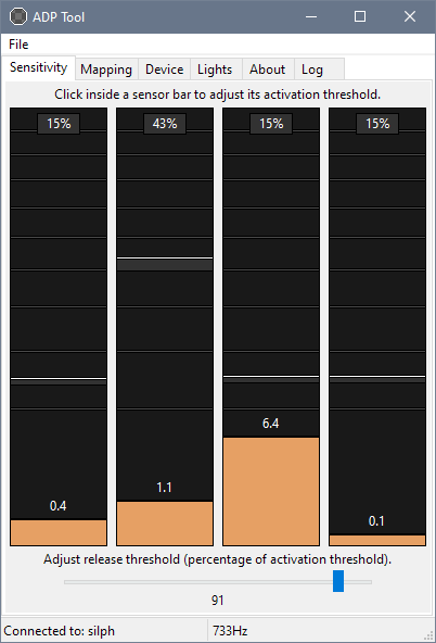
Yep, I changed the graph to y = √x so that the floating value gaps appeared less apart. It’s relatively easy enough to tweak the app to whatever you fancy.
And with that, the pad should be good to go!
Other Precautions & Findings
When I thought I was ready to write this article and be done with it in a day, it turns out it was really just the tip of the iceberg.
Accounting for sticky FSR padding
When a panel is stepped hard enough and then released, the sticky material of the FSR padding can grip onto the panel long enough before it peels itself off from the surface. This can be picked up on the readings as a slow drop back to its idle floating value.
Usually what I do once I put the panel back on is to step hard on it to see if any of the padding “dislodges” (you’ll hear a distinct ‘sticking’ sound) and the floating value spikes as a result. Typically, when this happens, putting pressure on the back panel won’t solve the issue, confirming the cause is more likely sticky padding.
As much as I wanted to keep it untouched, my solution was to affix a conveniently similarly sized sticky note to the top of the FSR padding. Of course, I had to do a retape to adjust for the technically increased sensitivity.
Whilst I was at it, I ensured that every padding had at least one layer of masking tape, to reduce the chances of it misbehaving with the panel and throwing the values off.
Panels are temperamental between opens
Kind of related to the above issue: if you plan to stream with these pads, try to get your panels as good as they can be before starting. Once you open them up, there’s no knowing whether the movement of the paddings will require you to do a retape – and then your presumed quick fix ends up putting a pause in your session (and your viewers’ interests) for a good several minutes.
The alternative? Simply readjust the thresholds. That’s why we switched to FSRs in the first place, no?
This problem also occurs with SMX (and therefore FSR pads in general), so it’s best just to not open them at all if you can avoid it. Instead, adjusting the tightness of the [back] screws should be enough to solve the problem.
Floating values are perfectly fine
Coming from people’s experiences with modded SMX pads, owners of these stages say there really isn’t a need to have perfect zero. Most of the times, modding for sub zero values typically comes with:
- The panel having less of a response range, i.e. when tapped with the same force, the peak value isn’t as high as compared to other panels,
- The value when a certain weight has been applied to it is significantly lower than the rest, i.e. on a 70% target for the dumbbell calibration the sensor reports something like 40%
That’s the reason why I’m content with ↑ averaging around 6.5 to 10. The floating value rarely ever exceeds 11, so I can confidently set the threshold to as low as 14 or 15.
[1] Yes, with an Uncle Roger accent.
Other FSR Mini Content
Here’s a link to my unboxing and software setup article.
A gameplay review will be written soon™ (when I get the chance to play instead of write).