FSR Mini v2: Unboxing & Setup
One early afternoon on the 22nd of December, 14 hours before Rhythm Technologies released their pads for sale the next morning, I woke up to a message in our chat: I forgot to drop this here – he posts the link – I’m thinking of grabbing one.
…And it only went downhill from there.
We knew the deal, if the within-a-minute SMX sell-out experience taught us something: make an account, save your details, do a test purchase. Failing to plan is planning to fail.
I never knew how many there were to start with; I must’ve presumed 50. By the time checkout was completed, five were left. Four. One.
Just six minutes and several seconds after 04:00, the v2 sold out.
I’m not waking up at 4am for this. If it’s sold out, then so be it, he said.
Not even a chance.
Pictures
FedEx estimated I’d get my shipment today or tomorrow as of when I wrote this (4/5 Jan ’23). I ended up receiving the package before the end of the year. Chill, bro 😅 Either way, I appreciated the speedy delivery.
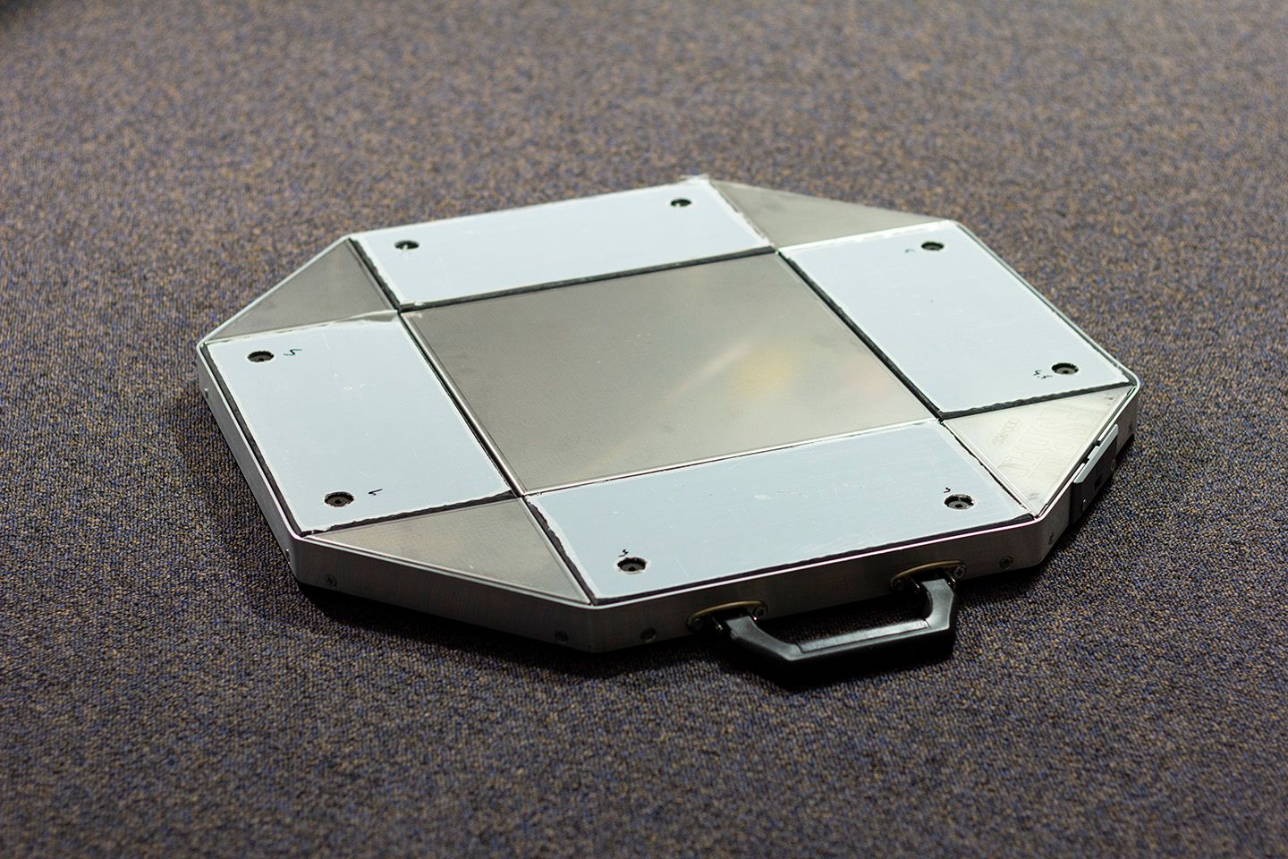


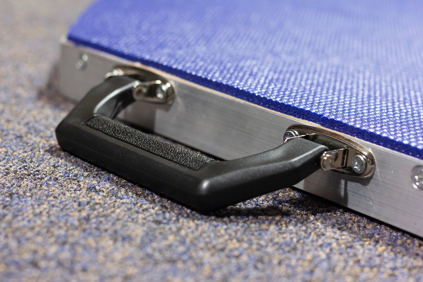
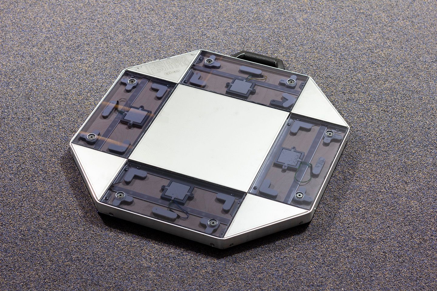
It arrived as-is inside a flat cardboard box with a USB C to A cable, the receipt + a thank you letter, and a small sticker. It has a reliable heft when I lift it by its handle – it’s probably more “portable” in the sense you can easily stash it in the back of a car and drive it around.
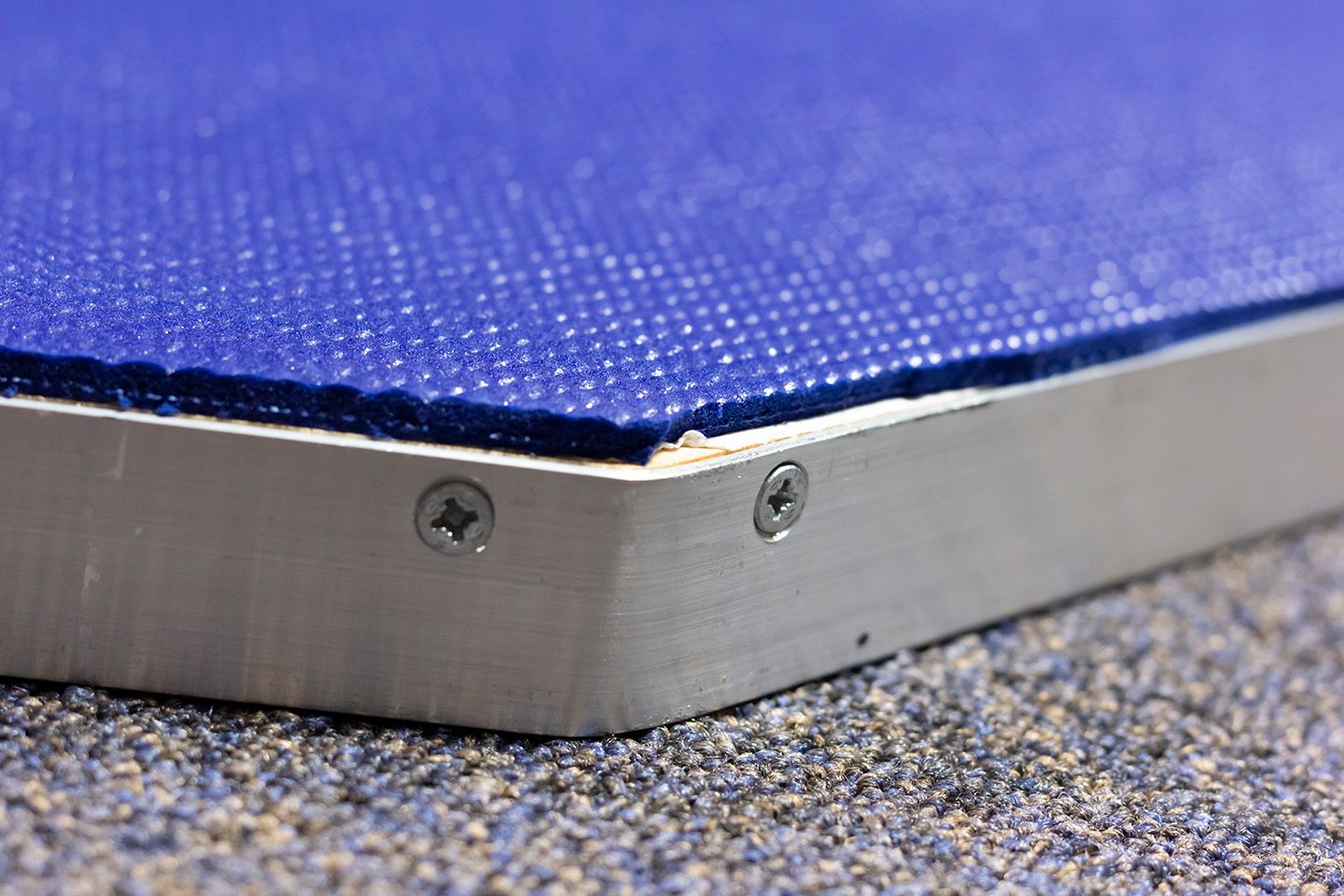
I did have initial doubts that an 8.5kg pad was heavy enough to prevent movement, but I reckon the rubber padding might just do the trick...
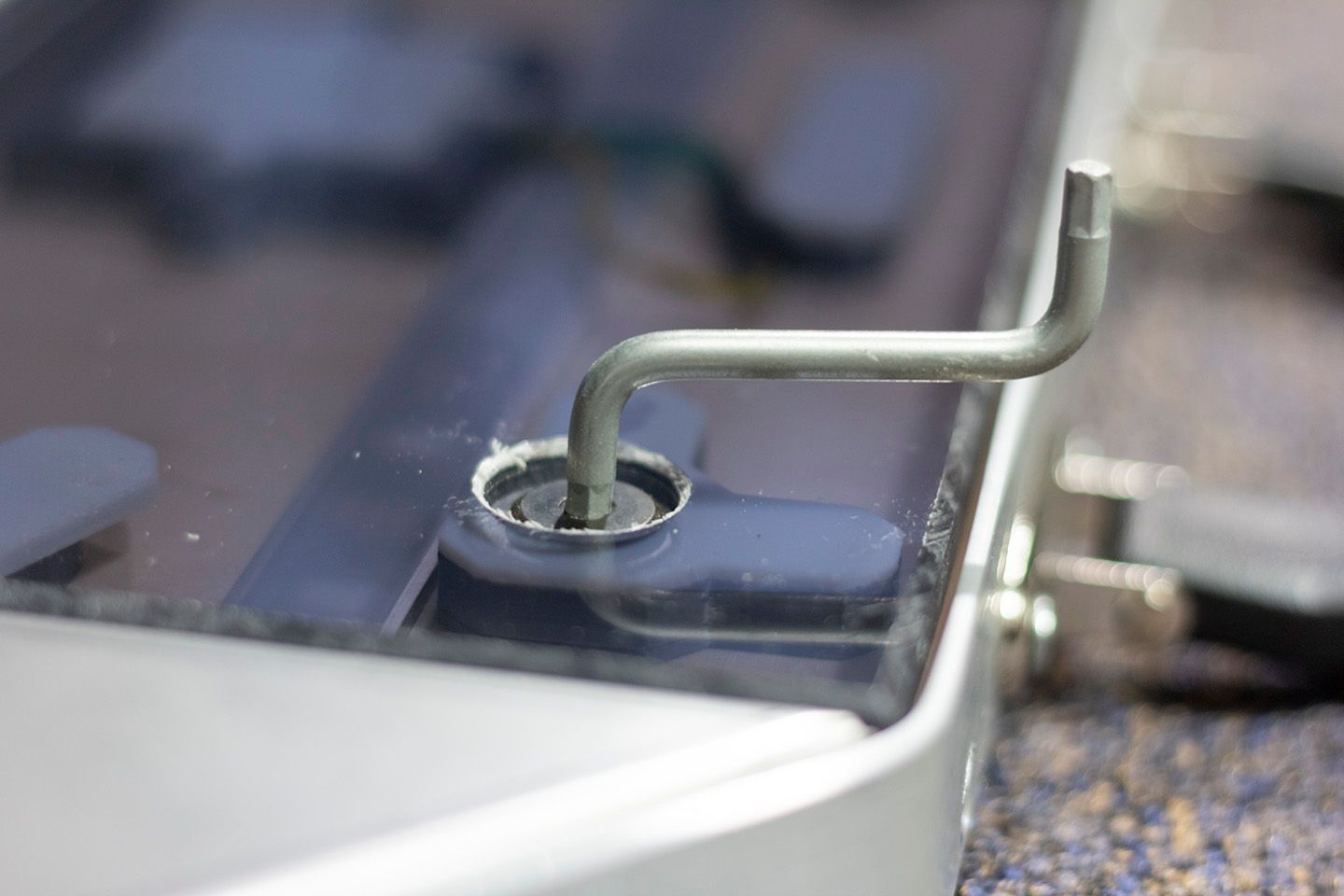
Off the protective stickers go... and whoops, seems like one of the L paddings came off during shipping. I went to search for one of the Allen keys that I used for assembling something from IKEA years back, and it did the job. These screws are a bit larger than the ones I use for the DDR cab at the arcade.
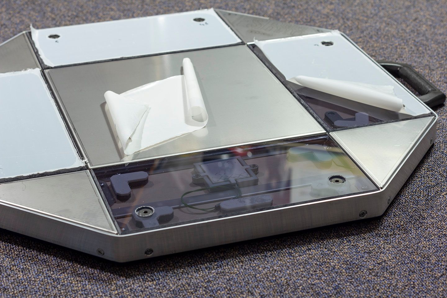
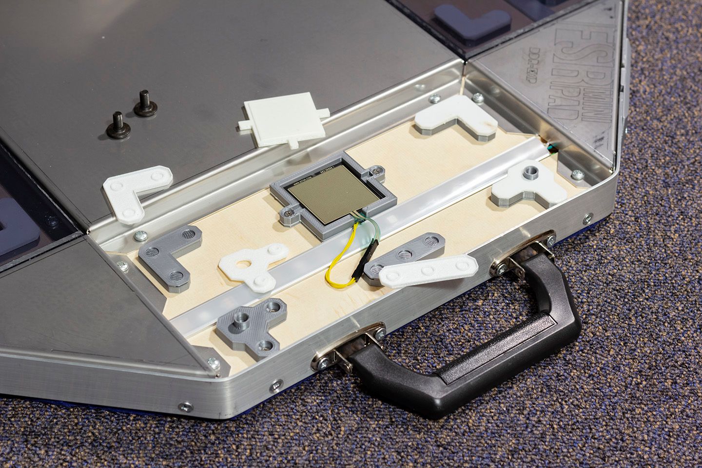
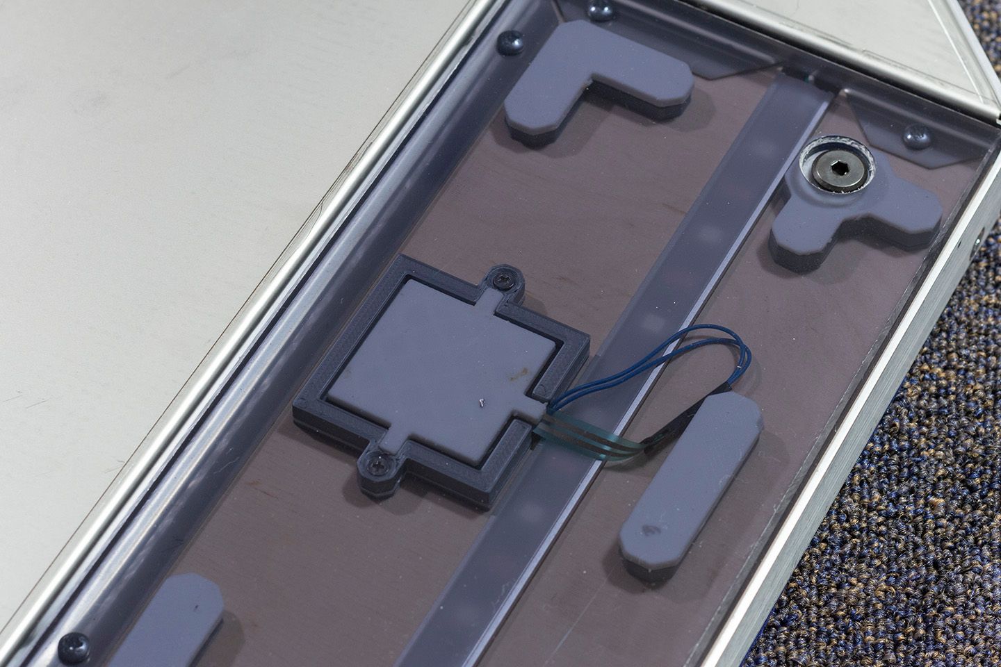
I like the ‘demonstrator’ aesthetic of the transparent panels and being able to see what’s inside. Not that you need to, though – I hope you’re not using the forbidden white powder on these...
I think an overlooked point of the v2’s design is how the FSR’s ribbon, at its current length, needs to twist around and to the side of the flat padding island. I suspect this, preventing the FSR from sitting perfectly flat against its housing, is partially responsible for the non-zero idle values (more on that below).
One thing I did notice is that the online shop’s picture of the pad has the flat padding removed to allow the ribbon to lie straight.
Ensure that the FSR padding’s two side ‘arms’ are pushed firmly into its slots, by the way. It should sit flush against the housing.
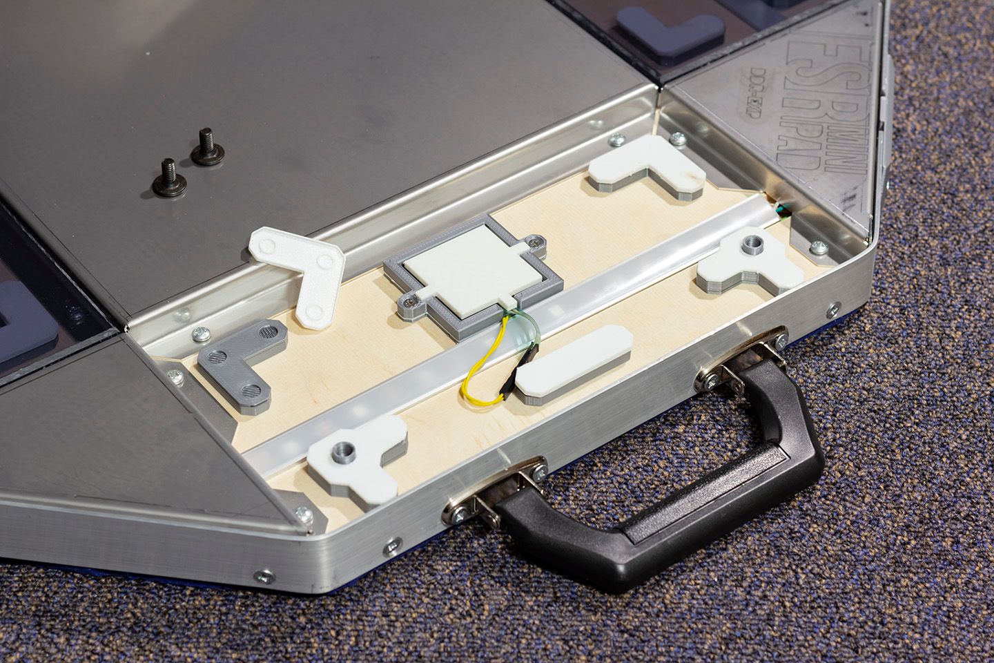
Also nit-picking, but you may have noticed the LED strip on the right hand side in the open panel photos isn’t sitting flush on the wood. It appears to be glued on, so I can’t move it into place.
It might also be a good idea to open up each panel to ensure everything’s clean between the panel and the padding.


It looks amazing with the LEDs! I think the next perfect product to accompany this is a zipper bag to hold the cable, tape and tools; maybe something simple like what YuanCon has with their controllers.
Building ADP Tool
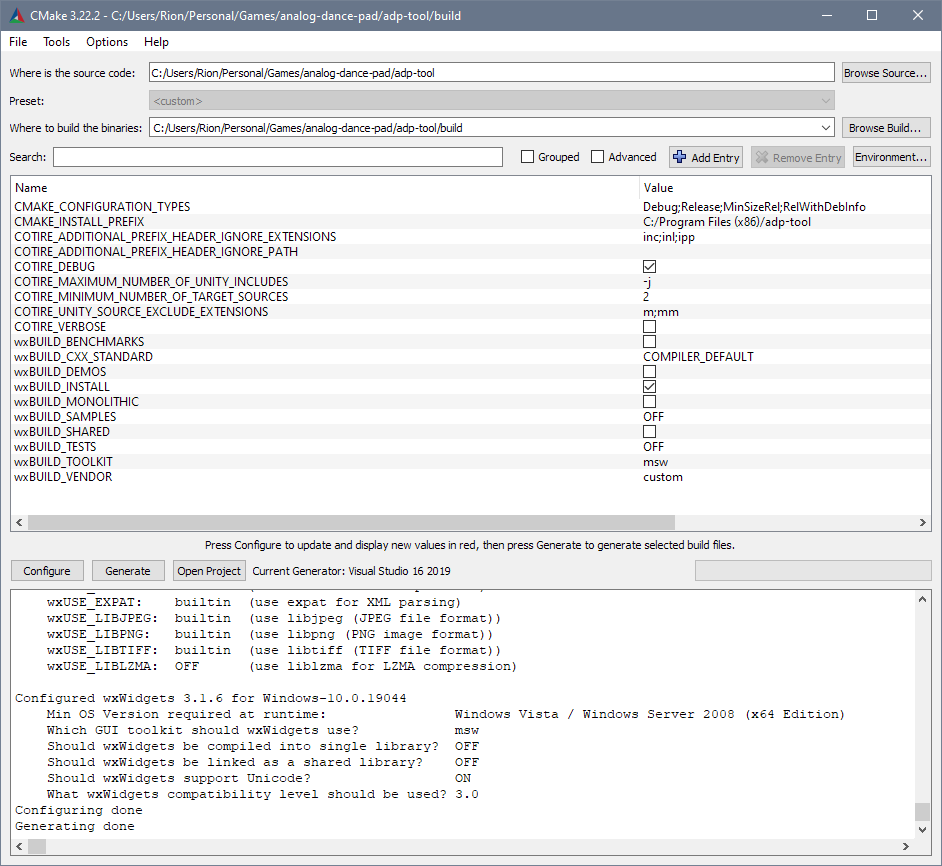
The product website suggested I use Electromuis’ fork (the guy who made these pads, btw) of analog-dance-pad. Whilst you can download the binary, it’s not that hard to build it yourself should you be keen in adding features to the app:
git clonehttps://github.com/electromuis/analog-dance-pad.git--recurse-submodules– be warned, the download will be about 1 GB and the build needs another 4 GB of disk space.- Configure the sauce and generate with
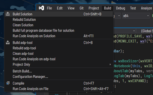
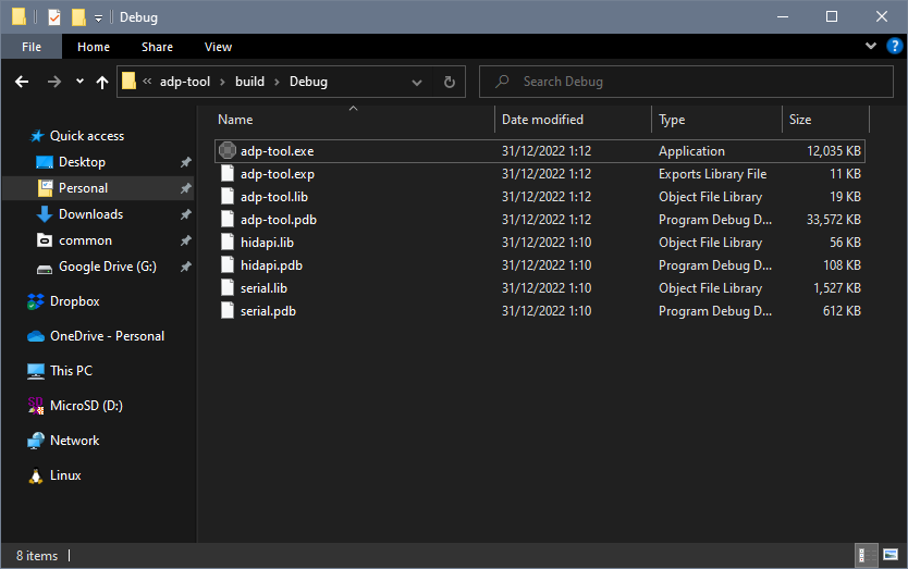
cmake. I had VS 2019 installed, so I used that. - Open the solution and hit build. Let it do its magic. Boom.
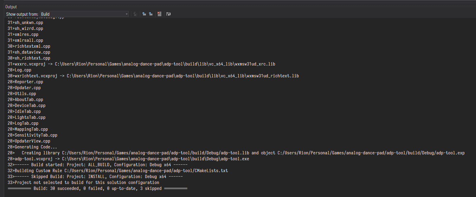
built stepmania before? it’s not that much different here
Most of ADP Tool’s code consists of the GUI interfacing to the underlying hardware controls. The source code is easy to understand and should be simple to tweak to your liking.
Mod Calibrating
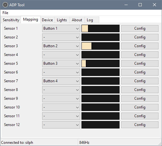
Out of the box, the sensors had uneven idle values, so I went straight ahead with tape fixing that up. Unfortunately, this means I wasn’t able to test it in stock condition. The left sensor (7 in the screenshot) was the only perfect one from the get go: stable 0 at idle, and the most sensitive out of the four.
I’ve been told that with Still Grey, Sujeet’s software implementation, and SMX pads, stable idle readings of 0 could mean the pad is too insensitive. You could say having some idle fluctuations (close to 0) are better ‘signs of health’, so to speak.
8/1/23 Update: Nope, spoke too soon. The moment I took out the panel and put it back whilst writing the tape mod article, the idle value shot up to 30%.
After the classic gruelling four hour modding session of learning the dynamics of how the tape interacts with the system, I placed 5lb (~2.3kg) weights directly on top of the sensor and adjusted each one in the mapping configuration so that their value was at 70%. Then, I reduced the sensitivity threshold as I see fit.
Configuring Lights
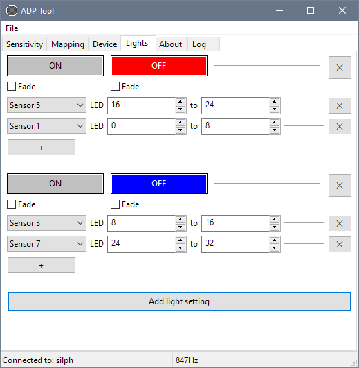
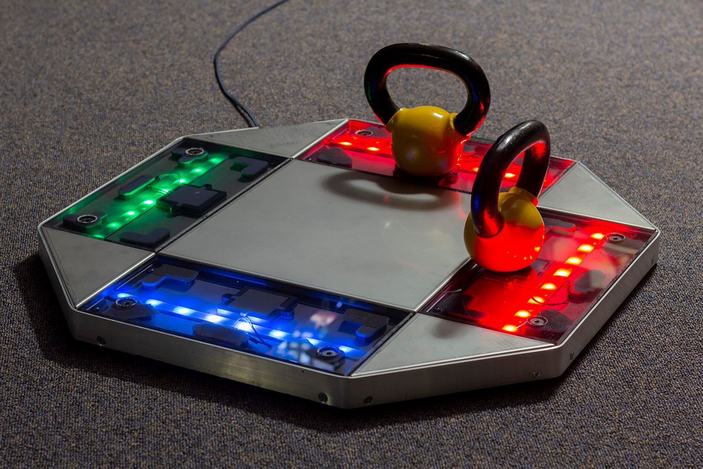
Light settings exist as a list of colour configurations, applied from top to bottom, that gets carried out when some sensor is in its off (released) or on (triggered) state. For each config, you specify the sensor(s) that will be associated with triggering those colours, along with the range of LEDs you want to apply them to. Out of the box, all the respective LEDs in the ↑/↓ panels are red, and the ←/→ panels are blue, in their off state. They directly switch to grey in their on state.
Fancy fadework
However, here’s where you can start getting creative: if you use the “fade” option, you can map gradients between the two states, i.e. have one gradient from 0 → x for off, and another from x → 1 for on. As shown in the screenshot, on and off states have their own fade setting; you’re not stuck with having the same for both.
Note that this means one of your gradients will transition very quickly if you set your sensitivity very low or very high. For example, if you have a sensor set to trigger at 10%, your off gradient only has the space of (“squeezed” between) 0 → 10% to change between the two colours.
As of software v1.3, the gradient stops only exist at their ends (i.e. 0 and 1). You can’t, for instance, create a black stop at 2% to account for dead zones.
My initial idea was that I wanted the LEDs from the centre to light up outwards. This can be done with gradients that have a lower stop set at 20%, 40%, 60% and 80%.
As I couldn’t do this, my compromise was to have multiple ramps of colours exponentially increase in luminance. Keep in mind Windows’ HSL ranges go from 0 to 240, and also how the order of these configs work as they are applied (and overwritten) from top to bottom.
| Setting | Gradient (HSL) | LED | Sensor / LED Indexes |
|---|---|---|---|
| A and B are the hues of two colours | |||
| Off F ✓ | A, 240, 2 → 15 | ■■■■■■■■ |
1: 0-8 5: 16-24 |
| Off F ✓ | A, 240, 15 → 30 | -■■■■■■- |
1: 1-7 5: 17-23 |
| Off F ✓ | A, 240, 30 → 60 | --■■■■-- |
1: 2-6 5: 18-22 |
| Off F ✓ | A, 240, 60 → 120 | ---■■--- |
1: 3-5 5: 19-21 |
| Off F ✓ | B, 240, 2 → 15 | ■■■■■■■■ |
3: 8-16 7: 24-32 |
| Off F ✓ | B, 240, 15 → 30 | -■■■■■■- |
3: 9-15 7: 25-31 |
| Off F ✓ | B, 240, 30 → 60 | --■■■■-- |
3: 10-14 7: 26-30 |
| Off F ✓ | B, 240, 60 → 120 | ---■■--- |
3: 11-13 7: 27-29 |
| For all above configs: On F ✗, trigger colour of your choice | |||
With the handle facing north, the light IDs start from the top left and go clockwise. Note that in the software, the index ranges are [x, y). For example, to light up only light 0 you would need to specify 0-1, not 0-0.
Sensor 1  ↑   0 (left)  to  8 (right)
Sensor 3  →   8 (up)    to 16 (down)
Sensor 5  ↓  16 (right) to 24 (left)
Sensor 7  ←  24 (down)  to 32 (up)
There’s More
I’ve documented my findings on the dynamics of the pad in regards to tape modding.
I haven’t had a chance to actually play on the pads just yet, because I’m busy trying to populate the site with articles that I still have to get to. When I’m done with that, I’ll then give my gameplay impressions.